SolarEdge gateway for commercial use (SE1000-CCG-G-S1)
SKU: 229120€157.02 (0% BTW)
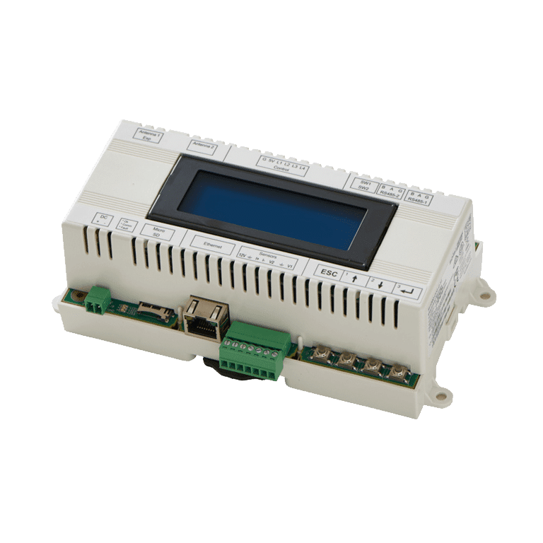
SolarEdge Commercial Gateway (SE1000-CCG-G-S1) – All-in-one communication gateway for commercial PV systems.
Connect RS485 inverters, energy meters and environmental sensors, send data via Ethernet to the monitoring platform
and control exports with the integrated Power Reduction Interface. DIN rail or wall mounting.
MPN: SE1000-CCG-G-S1
Bezorging op Thursday 9 April — voor €6.95 verzonden (met 0% btw).
32 in stock
