


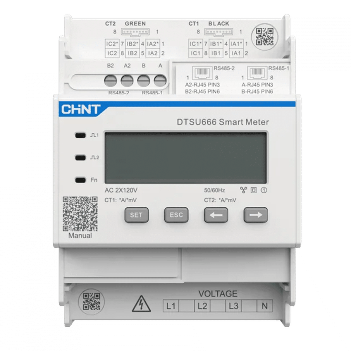
Growatt Smart Meter TPM-6CT-C-EU
SKU: 240456€225.00 – €270.00Price range: €225.00 through €270.00 (21% BTW)
MPN: MR00.0037600
Growatt Smart Meter TPM-6CT-C-EU – Smart 3-phase Meter for Efficient Energy Management
The Growatt Smart Meter TPM-6CT-C-EU is an advanced three-phase smart meter that is a perfect match for Growatt’s APX battery systems and inverters. With this meter it is possible to scale up existing PV installations of more than 8 kW with Growatt APX batteries, even on 3-phase systems.
Key Features
- Efficient Grid Management and Export Limitation
The TPM-6CT-C-EU measures both the import and the export of energy from and to the grid. This makes export limitation possible, so that surplus energy can be used optimally without overloading the grid. - Widely Applicable with Growatt Storage Systems and EV Chargers
This smart meter works seamlessly together with Growatt’s energy storage systems and EV chargers, which ensures integrated and efficient energy management for both domestic and commercial applications. - Accurate Measurement and Reliable Connectivity
The TPM-6CT-C-EU offers accurate measurements with 0,5% voltage and current accuracy and 1% power accuracy. Thanks to Modbus RTU communication there is a stable and fast connection with the inverter for real-time data exchange.
Installation and Technical Specifications
- Mounting: Easy to install on a DIN rail.
- Input voltage: Suitable for voltages of 100-415V (3P3W) L-L and 57.7-240V (3P4W) L-N.
- Operating temperature: Designed to operate between -25°C and +55°C.
- Communication: Equipped with RS485 communication and Modbus RTU protocol, with a transfer rate of 9600 baud.
The Growatt Smart Meter TPM-6CT-C-EU is the ideal choice for anyone who wants to expand their 3-phase PV system with a Growatt battery and get the most out of export limitation and efficient cooperation with other Growatt devices.
Connecting CT clamps to the correct phase
In a 3-phase system it is important that every CT clamp belongs to the correct phase.
That means that CT1 belongs to L1, CT2 to L2 and CT3 to L3.
The energy meter, inverter or battery controller combines the current measurement of the CT clamp with the voltage measurement of that same phase.
If a CT clamp is fitted around the wrong phase, the system may well see current, but the power is calculated incorrectly.
As a result, consumption, feed-in, import, export and battery control can be displayed or controlled incorrectly.
How do you check whether the CT clamp is on the correct phase?
You can check this with a multimeter in AC voltage mode.
The idea is simple: you compare the conductor the CT clamp is fitted around with the voltage input of the phase that CT belongs to.
For example, measure between:
- the conductor CT1 is fitted around and the L1 voltage connection
- the conductor CT2 is fitted around and the L2 voltage connection
- the conductor CT3 is fitted around and the L3 voltage connection
If you measure between the same phase points, the voltage difference is approximately 0 V up to a few volts.
If you measure between two different phases, you usually measure approximately 400 V.
Practical rule of thumb
- 0 V or almost 0 V = the same phase
- approximately 400 V = a different phase
Example: do you measure approximately 400 V between the conductor of CT1 and L1, but approximately 0 V between that same conductor and L2?
Then CT1 is not fitted around L1, but around L2.
Which voltages should you normally expect?
In a normal 3-phase installation in the Netherlands you usually see approximately:
- L1 – N ≈ 230 V
- L2 – N ≈ 230 V
- L3 – N ≈ 230 V
- L1 – L2 ≈ 400 V
- L2 – L3 ≈ 400 V
- L1 – L3 ≈ 400 V
These measurements help you to check whether the voltage connections have been wired logically and whether the CT clamps are on the correct phase.
Also check with a load test
An extra practical check is a load test. Switch on a clear single-phase load, for example a kettle, work light or electric heater,
and look at the meter, in the app or in the monitoring to see on which phase the consumption rises.
- Load switched on at L1 → only L1 should rise noticeably
- Load switched on at L2 → only L2 should rise noticeably
- Load switched on at L3 → only L3 should rise noticeably
If the load appears on the wrong phase, the CT clamps have been swapped over or the link between current measurement and voltage measurement is not correct.
Also pay attention to the direction of the CT clamp
Besides the correct phase, the direction is important too. Many CT clamps have an arrow on them.
That arrow indicates how the current direction is interpreted. If the CT clamp is fitted the wrong way round, the system may reverse import and export.
Do you see negative values or illogical feed-in during normal consumption? Then there is a good chance that the CT clamp is fitted the wrong way round.
What else should you look out for?
- Always fit the CT clamp around one single conductor, usually the phase.
- Not around a complete cable with phase and neutral together, otherwise the magnetic fields cancel each other out.
- For 3-phase systems: keep to the order CT1-L1, CT2-L2, CT3-L3.
- Click the CT clamp fully closed.
- If measurement values look strange, always check the phase pairing first and then the direction.
These measurements are often carried out in the meter cupboard on live phase conductors. Only use suitable measuring equipment and work safely.
If you are in any doubt about the measurement or the connection, have the work carried out by a qualified installer.
Please note: CT clamps are not simply interchangeable
A CT clamp may look like a simple measuring clip, but technically it is an important part of the measurement.
The inverter, energy meter or home battery expects a very specific signal from the CT clamp. That is why a CT clamp is not simply
interchangeable with one of another brand or type.
A CT clamp measures the current through a cable and converts it into a small measuring signal. That signal can be a small current, for example
50 mA, or a small voltage, such as 333 mV or 1 V. The connected device then converts
that measuring signal back to the actual current in amperes.
If the ratio or the output signal is not correct, the system measures incorrectly. With a normal energy measurement that is annoying enough, but with
a home battery, dynamic control or export limitation this can cause the system to control in exactly the wrong direction.
Which properties have to match?
- CT ratio, for example 100A/50mA, 120A/40mA or 100A/333mV.
- Output type: current output in mA or voltage output in mV/V.
- Maximum measuring current, for example 100A, 120A or 250A.
- Burden resistor: is the measuring resistor inside the CT clamp or inside the device?
- Pinout and connector: a connector that fits is not automatically electrically identical.
- Phase direction and polarity: important for import, export, charging and discharging.
- Accuracy and phase shift: especially important for power measurement.
Therefore only use this CT clamp with devices for which it is suitable according to the manufacturer. In doubt? Then it is better to use the original
CT clamp or check the specifications carefully before connecting.
How does a CT clamp work?
CT stands for Current Transformer. Inside the CT clamp there is a magnetic core with a coil around it.
The cable you click the clamp around forms the primary side of the transformer. Usually that is a single winding: the phase cable itself.
When alternating current flows through the cable, an alternating magnetic field is created around that cable. The core of the CT clamp picks up this
magnetic field. As a result, a small electrical signal is generated in the coil of the CT clamp. The more current that flows through the cable,
the larger the measuring signal becomes.
Why can the wrong CT clamp cause problems?
The wrong CT clamp can cause the device to measure a value that is too high, too low or even reversed. With solar panels and
home batteries that can have considerable consequences.
- The battery charges when it should actually be discharging.
- The battery discharges while there is in fact surplus solar power.
- The inverter thinks power is being fed in while power is actually being drawn.
- Export limitation does not work properly or reacts too late.
- The displayed consumption or feed-in is not correct.
- A 3-phase system measures the phases incorrectly or mixes them up.
How can you find out what kind of CT clamp you have?
Always start with the label or the datasheet. On many CT clamps the ratio is stated directly, for example:
- 100A/50mA – current output
- 120A/40mA – current output
- 100A/333mV – voltage output
- 250A/5A – industrial current transformer
- 2000:1 – ratio between primary and secondary current
Does the CT clamp say mA? Then it is usually a CT with a current output. Does it say mV or V?
Then it is usually a CT with a voltage output, often with a built-in measuring resistor.
With a multimeter you can measure the resistance between the two wires of the CT clamp. This does not directly tell you the exact CT ratio,
but it can help you to see whether the clamp is open-circuit and whether a coil or built-in measuring resistor is probably present.
If you want to check the ratio, you can test the CT clamp with a known load. With a CT clamp with a voltage output you measure with
the multimeter in AC mV or AC V. If you measure approximately 33 mV at 10 A, for example, that works out at
approximately 333 mV at 100 A. That points to a 100A/333mV CT clamp.
With a CT clamp with a current output you usually have to work with a suitable burden resistor for a safe and correct measurement. With it you convert
the secondary current into a measurable voltage. Only do this if you know what you are doing, and prevent a classic current CT from being left open
while current is flowing through the primary cable.
What should you pay attention to when connecting?
- Fit the CT clamp around one single conductor, usually the phase. Not around a complete cable with phase and neutral together.
- Pay attention to the arrow direction on the CT clamp. The direction determines how import and export are interpreted.
- For 3-phase systems: link CT1 to L1, CT2 to L2 and CT3 to L3.
- Check the phase sequence if values are displayed as strange or negative.
- Click the CT clamp fully closed. A poorly closed core can give inaccurate measurements.
- Do not simply extend CT cables. Extra length, poor connections or the wrong cables can affect the measurement.
- Fit the CT at the correct measuring point, usually at the start of the installation, so that the system can measure all consumption and feed-in.
Only work in the meter cupboard if you know what you are doing. CT clamps are often fitted around main or phase conductors where dangerous voltages
and currents are present. Switch off safely where possible and, if in doubt, have the work carried out by a qualified installer.
| Weight | 2.19 kg |
|---|---|
| Brand | Growatt |
| Current | 100A, 250A |
